


Mon - Sat 8:00 - 17:30, Sunday - CLOSED
District Cooling Services
District cooling is a centralized cooling approach designed to serve large buildings, campuses, mixed-use developments, and infrastructure projects through a shared chilled-water network. Instead of relying on separate cooling plants for each building, a district cooling system produces chilled water at a central plant and distributes it through an insulated piping network to connected facilities, where Energy Transfer Stations (ETS) transfer cooling to the building’s internal systems.
Afzali provides District Cooling Services covering consulting, engineering, design, construction, installation, testing, and commissioning. Our scope can include cooling demand assessment, district cooling plant engineering, chilled-water network design and installation, ETS integration, equipment selection, hydraulic analysis, control systems, and performance optimization.
Contact our experts directly via email and we will get back to you shortly with the best solutions and competitive prices.
How Do Afzali’s District Cooling Services Work?
Afzali delivers district cooling projects through an integrated consulting, engineering, contracting, installation, and commissioning process. Rather than treating the plant, chilled-water network, ETS units, and control systems as separate packages, we coordinate them as one complete cooling infrastructure from the early project stage through final handover and performance optimization.
1. Project Assessment & Consultation
Every project begins with a technical assessment of the development, existing infrastructure, cooling requirements, construction conditions, and future expansion plans.
At this stage, Afzali reviews:
- Project type and development scale
- Existing or planned cooling infrastructure
- Preliminary cooling demand
- Site and utility conditions
- Project phasing and future expansion
- Technical and operational requirements
The objective is to establish a realistic project scope before detailed engineering or construction begins.
2. Engineering & Design
Based on the project assessment, Afzali develops the district cooling engineering concept and technical design required for execution.
The engineering scope may cover:
- District cooling plant configuration
- Chilled-water distribution network
- Energy Transfer Stations (ETS)
- Equipment selection
- Hydraulic design
- Electrical and control integration
- Technical drawings and specifications
Detailed engineering calculations and design methodology are developed in the dedicated engineering stage described below.
3. Construction & Installation
Once the design is approved for execution, Afzali supports or performs the construction and installation scope required to convert the engineering design into an operational system.
The scope may include:
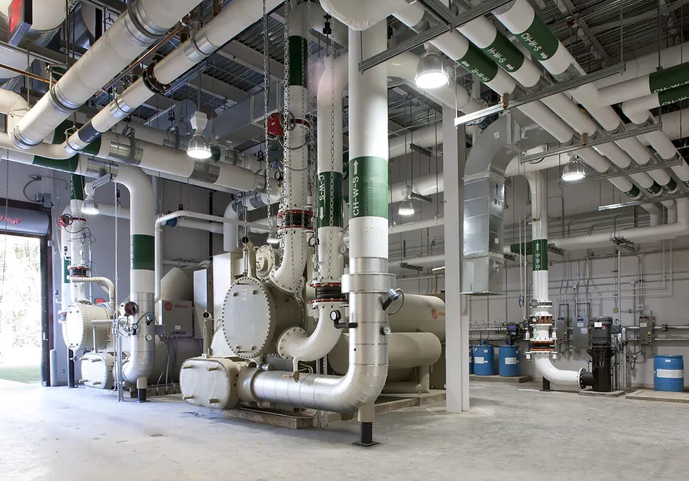
- District cooling plant mechanical works
- Chiller, pump, and cooling tower installation
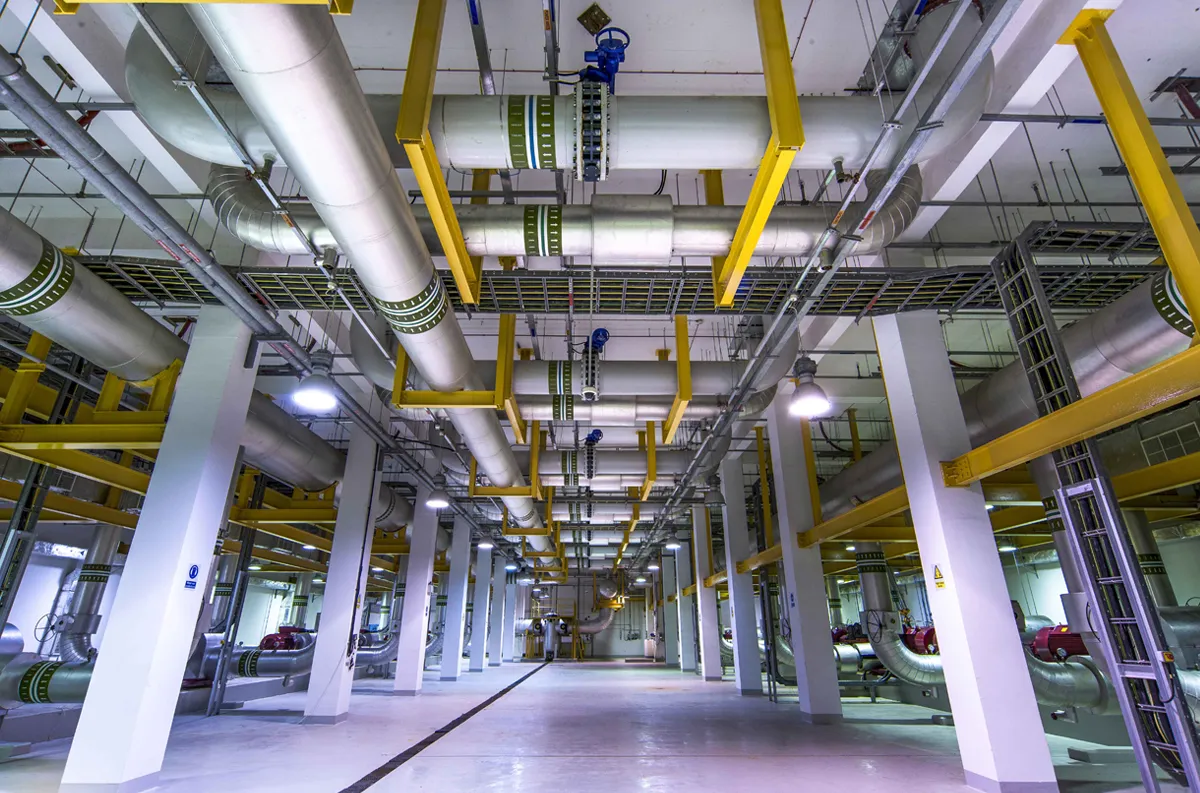
- Chilled-water piping installation
- ETS construction and installation
- Insulation and cladding
- Electrical works
- Instrumentation and control integration
- Coordination between mechanical, electrical, and civil works
Construction activities are coordinated with the approved engineering documentation to reduce site conflicts and maintain the intended system performance.
4. Testing & Commissioning
Before the system enters normal operation, installed equipment and networks are tested individually and then verified as an integrated district cooling system.
Typical activities include:
- Pressure and hydrostatic testing
- Network flushing and water treatment
- Hydraulic balancing
- Chiller and pump functional testing
- ETS testing
- Control sequence verification
- SCADA and BMS testing
- Performance verification
- Final commissioning and handover support
The objective is to verify that the installed system operates according to the approved design and intended operating strategy.
5. Monitoring & Performance Optimization
After commissioning, Afzali can support the monitoring and optimization of the district cooling system using operational data from the plant, network, ETS units, and control systems.
Important parameters may include:
- Chilled-water supply and return temperatures
- Flow rates
- Differential pressure
- Cooling demand
- Equipment operating status
- Energy consumption
- Alarm conditions
Why Afzali?
Trusted District Cooling Services Consultation

Project Strategy
End-to-end District Cooling Services

Compliance
HACCP & regulations fully met

Vendor-Neutral
Unbiased recommendations

ROI-Focused
Maximize your investment

Reliability
System reliability and operational stability
District Cooling Services Design & Engineering Process
District cooling engineering begins with one fundamental requirement: the plant, network, ETS units, and control strategy must be designed as one hydraulically and thermally coordinated system. Afzali’s engineering process develops the project step by step, beginning with cooling demand and progressing through plant design, hydraulic calculations, ETS engineering, control strategy, and construction documentation.
Step 1: Cooling Demand Assessment & Load Analysis
The engineering process begins by establishing the actual cooling demand of the development.
The analysis considers:
- Peak cooling demand
- Part-load operating conditions
- Building operating schedules
- Diversity between connected buildings
- Project development phases
- Future cooling demand
- Required system redundancy
- UAE ambient conditions
The objective is to establish a realistic design load rather than simply adding together the nominal cooling capacities of all connected buildings.
This design load becomes the basis for plant capacity, chilled-water flow, network sizing, and equipment selection.
Step 2: District Cooling Plant Capacity & Configuration
Once the cooling demand is established, the central plant is configured according to required capacity, operating flexibility, efficiency targets, redundancy, and future expansion.
Engineering decisions may include:
- Number and capacity of chillers
- Chiller staging strategy
- Cooling tower configuration
- Primary and distribution pumping arrangement
- Standby equipment requirements
- Plant equipment layout
- Heat-rejection requirements
- Electrical capacity requirements
A properly configured plant should be able to respond efficiently to changing demand rather than operating efficiently only at peak design load.
Step 3: Chilled-Water Flow & Hydraulic Design
The required chilled-water flow is determined from cooling demand and the selected design temperature difference.
Hydraulic engineering then evaluates:
- Required flow rates
- Pipe sizing
- Network velocity
- Pressure losses
- Static and dynamic pressure conditions
- Critical hydraulic paths
- Pump head requirements
- Differential-pressure control
- Network expansion requirements
The objective is to ensure sufficient chilled-water flow reaches every connected ETS without excessive pumping energy or unstable network pressure.
Step 4: Chilled-Water Distribution Network Design
After the hydraulic criteria are established, the physical distribution network is developed.
The design may include:
- Supply and return routing
- Pre-insulated piping
- Main and branch sizing
- Isolation valve locations
- Valve chambers
- Network interfaces
- Expansion provisions
- Drainage and venting points
- Testing requirements
Particular attention is given to constructability, accessibility, pressure losses, future connections, and coordination with other underground infrastructure.
Step 5: Energy Transfer Station (ETS) Engineering
The ETS forms the thermal and hydraulic interface between the district cooling network and each connected building.
Engineering calculations typically address:
- Required cooling capacity
- Primary chilled-water flow
- Secondary chilled-water flow
- Plate heat exchanger sizing
- Design temperature approach
- Pressure losses
- Control valve selection
- Differential-pressure requirements
- Energy-metering requirements
- Temperature and flow instrumentation
The ETS should transfer the required cooling capacity while preventing instability in either the district cooling network or the building’s internal chilled-water system.
Read More: District Cooling Solutions for Large Facilities in Dubai
Step 6: Pumping Strategy & Differential Pressure Control
Pumping design is critical because district cooling networks operate under continuously changing demand.
The engineering strategy may include:
- Primary pumping
- Distribution pumping
- Variable-speed drives
- Differential-pressure sensors
- Critical-point pressure control
- Pump sequencing
- Minimum-flow requirements
- Operating redundancy
The control strategy should provide adequate pressure to the hydraulically critical parts of the network while avoiding unnecessary pump energy.
Step 7: Control, Automation & Monitoring Architecture
The mechanical design is integrated with a control architecture that coordinates plant equipment, pumping, network conditions, and ETS operation.
Typical monitoring and control points include:
- Chiller operating status
- Supply and return temperatures
- Flow rates
- Differential pressure
- Cooling demand
- Pump speed and status
- Cooling tower operation
- ETS performance
- Energy consumption
- System alarms
PLC, SCADA, BMS, and energy-metering platforms can be integrated according to the project’s operational requirements.
Step 8: Engineering Documentation & Construction Package
The final design must provide enough technical information for procurement, construction, testing, and commissioning.
Engineering deliverables may include:
- Design calculations
- Equipment schedules
- Technical specifications
- Plant layouts
- Chilled-water network layouts
- P&IDs
- ETS schematics
- Hydraulic calculations
- Control philosophy
- Instrumentation requirements
- Installation details
- Testing and commissioning requirements
Contact our experts directly via email and we will get back to you shortly with the best solutions and competitive prices.
District Cooling Equipment
A district cooling system relies on a combination of cooling, pumping, heat-transfer, control, and monitoring equipment working as one integrated system. Equipment selection should be based on cooling demand, hydraulic conditions, operating temperatures, redundancy requirements, energy efficiency, maintainability, and future capacity expansion rather than nominal capacity alone.
Find Out More: District Cooling Solutions in Bur Dubai
equipment used in district cooling systems:
District Cooling Equipment | Main Function | Key Engineering Consideration |
Water-Cooled Chillers | Produce chilled water for the district cooling network | Capacity, part-load efficiency, redundancy, and staging |
Cooling Towers | Reject heat from the condenser-water circuit to the environment | UAE ambient conditions, approach temperature, water consumption, and heat-rejection capacity |
Primary Chilled-Water Pumps | Circulate chilled water through the chiller plant | Required flow, pump head, efficiency, and operating configuration |
Distribution Pumps | Deliver chilled water through the district cooling network | Network pressure losses, differential pressure, variable demand, and VSD control |
Condenser-Water Pumps | Circulate water between chillers and cooling towers | Condenser flow requirements, pump efficiency, and system resistance |
Plate Heat Exchangers | Transfer cooling between the district network and the building system at the ETS | Cooling capacity, approach temperature, pressure drop, and fouling allowance |
Control Valves | Regulate chilled-water flow according to actual cooling demand | Valve authority, flow control, differential pressure, and response stability |
Energy Meters | Measure delivered cooling energy at connected facilities | Flow accuracy, temperature measurement, calibration, and system integration |
Expansion & Pressurization Systems | Maintain stable system pressure and accommodate water-volume changes | System volume, pressure range, elevation, and network operating conditions |
Air & Dirt Separators / Strainers | Remove trapped air and contaminants from the water circuit | Pressure drop, filtration level, maintenance access, and water quality |
Water Treatment Systems | Protect piping, chillers, cooling towers, and heat exchangers from corrosion, scaling, and biological growth | Water chemistry, system materials, operating temperature, and maintenance strategy |
VFD / VSD Systems | Adjust pump, fan, and selected equipment speed according to real operating demand | Part-load performance, control logic, minimum operating limits, and energy optimization |
PLC & SCADA Systems | Coordinate plant operation, monitoring, alarms, sequencing, and performance analysis | Control architecture, communication protocols, redundancy, cybersecurity, and data availability |
Contact Afzali for a System Consultation
Contact Afzali’s expert hvac consultants today and receive strategic guidance tailored to your business.
Frequently Asked Questions
How is the required capacity of a district cooling plant calculated?
District cooling plant capacity is determined from the diversified cooling demand of all connected buildings rather than simply adding their individual peak loads. Engineers consider peak and part-load demand, operating schedules, diversity factors, future development phases, system redundancy, and expected network losses before defining the final plant capacity.
How is chilled-water flow calculated in a district cooling system?
Required chilled-water flow is calculated from the cooling load and the design temperature difference between chilled-water supply and return. A larger effective ΔT generally allows the same cooling capacity to be delivered with lower water flow, while poor ΔT performance can increase flow requirements and pumping energy.
What is an Energy Transfer Station (ETS) in district cooling?
An Energy Transfer Station is the interface between the district cooling network and a connected building. It typically uses plate heat exchangers to transfer cooling from the primary district network to the building’s secondary chilled-water system while maintaining hydraulic separation between the two circuits.
How is a district cooling chilled-water network sized?
Network sizing is based on required flow, acceptable water velocity, pressure losses, available differential pressure, pipe length, elevation, future connections, and the hydraulic requirements of the most critical ETS. Engineers evaluate both normal and part-load conditions before selecting pipe diameters.